

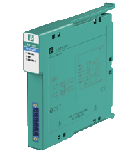
Digital Output with Position Feedback LB2117E
- 1-channel
- 1 digital output, 2 digital inputs
- Mounting in Zone 2, Class I/Div.2 or in the safe area
- Inputs and output Ex ia
- Line fault detection switched on and off
- Positive or negative logic selectable
- Simulation mode for service operations (forcing)
- Permanently self-monitoring
- Output with watchdog
- Output with bus-independent safety shutdown
- Module can be exchanged under voltage


Please note: All product-related documents, such as certificates, declarations of conformity, etc., which were issued prior to the conversion under the name Pepperl+Fuchs GmbH or Pepperl+Fuchs AG, also apply to Pepperl+Fuchs SE.
Folhas de dados: Dados técnicos do LB2117E
| Slots | ||
|---|---|---|
| Occupied slots | 1 | |
| Supply | ||
| Connection | backplane bus | |
| Rated voltage | Use only in connection with the power supplies LB9*** | |
| Power dissipation | 1.3 W | |
| Power consumption | 1.85 W | |
| Internal bus | ||
| Connection | backplane bus | |
| Interface | manufacturer-specific bus to standard com unit | |
| Digital input | ||
| Number of channels | 2 | |
| Sensor interface | ||
| Connection | NAMUR sensor | |
| Connection [2] | volt-free contact | |
| Connection | channel I: 2+, 5-; channel II: 3+, 6- | |
| Rated values | acc. to EN 60947-5-6 (NAMUR) | |
| Switching point/switching hysteresis | 1.2 ... 2.1 mA / ± 0.2 mA | |
| Voltage | 8.2 V | |
| Internal resistor | 1 kΩ | |
| Line fault detection | can be switched on/off for each channel via configuration tool | |
| Connection | mechanical switch with additional resistors (see connection diagram) proximity sensors without additional wiring | |
| Short-circuit | < 360 Ω | |
| Open-circuit | < 0.35 mA | |
| Minimum pulse duration | 1 ms | |
| Digital output | ||
| Number of channels | 1 | |
| Suitable field devices | ||
| Field device | Solenoid Valve | |
| Field device [2] | audible alarm | |
| Field device [3] | visual alarm | |
| Connection | channel I: 1+, 4- | |
| Internal resistor | 131 Ω | |
| Current limit | 50 mA | |
| Open loop voltage | 16.5 V | |
| Line fault detection | can be switched on/off for each channel via configuration tool , also when turned off (every 2.5 s the valve is turned on for 2 ms) | |
| Short-circuit | < 50 Ω | |
| Open-circuit | > 10 kΩ | |
| Response time | 10 ms (depending on bus cycle time) | |
| Watchdog | within 0.5 s the device goes in safe state, e.g. after loss of communication | |
| Indicators/settings | ||
| LED indication | Power LED (P) green: supply Diagnostic LED (I) red: module fault , red flashing: communication error , white: fixed parameter set (parameters from com unit are ignored) , white flashing: requests parameters from com unit Status LED (O: output, I1: input 1, I2: input 2) red: line fault (lead breakage or short circuit) , yellow: state of digital I/O (0/1) |
|
| Coding | optional mechanical coding via front socket | |
| Directive conformity | ||
| Electromagnetic compatibility | ||
| Directive 2014/30/EU | EN 61326-1:2013 | |
| Conformity | ||
| Electromagnetic compatibility | NE 21 | |
| Degree of protection | IEC 60529 | |
| Environmental test | EN 60068-2-14 | |
| Shock resistance | EN 60068-2-27 | |
| Vibration resistance | EN 60068-2-6 | |
| Damaging gas | EN 60068-2-42 | |
| Relative humidity | EN 60068-2-78 | |
| Ambient conditions | ||
| Ambient temperature | -40 ... 60 °C (-40 ... 140 °F) | |
| Storage temperature | -40 ... 85 °C (-40 ... 185 °F) | |
| Relative humidity | 95 % non-condensing | |
| Altitude | max. 2000 m | |
| Shock resistance | shock type I, shock duration 11 ms, shock amplitude 15 g, number of shocks 18 | |
| Vibration resistance | frequency range 10 ... 150 Hz; transition frequency: 57.56 Hz, amplitude/acceleration ± 0.075 mm/1 g; 10 cycles frequency range 5 ... 100 Hz; transition frequency: 13.2 Hz amplitude/acceleration ± 1 mm/0.7 g; 90 minutes at each resonance |
|
| Damaging gas | designed for operation in environmental conditions acc. to ISA-S71.04-1985, severity level G3 | |
| Mechanical specifications | ||
| Degree of protection | IP20 when mounted on backplane | |
| Connection | removable front connector with screw flange (accessory) wiring connection via spring terminals (0.14 ... 1.5 mm2) or screw terminals (0.08 ... 1.5 mm2) |
|
| Mass | approx. 110 g | |
| Dimensions | 16 x 100 x 102 mm (0.63 x 3.9 x 4 inch) | |
| Data for application in connection with hazardous areas | ||
| EU-type examination certificate | EXA 16 ATEX 0025X | |
| Marking |  II 3(1) G Ex nA [ia Ga] IIC T4 Gc II (1) D [Ex ia Da] IIIC I (M1) [Ex ia Ma] I II 3(1) G Ex nA [ia Ga] IIC T4 Gc II (1) D [Ex ia Da] IIIC I (M1) [Ex ia Ma] I |
|
| Input | ||
| Voltage | 10 V | |
| Current | 13 mA | |
| Power | 33 mW (linear characteristic) | |
| Internal capacitance | 1.2 nF | |
| Internal inductance | 0 mH | |
| Output | ||
| Voltage | 17.8 V | |
| Current | 162 mA | |
| Power | 751 mW | |
| Internal capacitance | 12 nF | |
| Internal inductance | 0 mH | |
| Galvanic isolation | ||
| Input/power supply, internal bus | safe electrical isolation acc. to EN 60079-11, voltage peak value 375 V | |
| Output/power supply, internal bus | safe electrical isolation acc. to EN 60079-11, voltage peak value 375 V | |
| Directive conformity | ||
| Directive 2014/34/EU | EN IEC 60079-0:2018+AC:2020 EN 60079-11:2012 EN 60079-15:2010 |
|
| International approvals | ||
| ATEX approval | EXA 16 ATEX 0025X | |
| UL approval | E106378 | |
| Control drawing | 116-0426 (cULus) | |
| IECEx approval | IECEx EXA 16.0010X | |
| Approved for | Ex nA [ia Ga] IIC T4 Gc [Ex ia Da] IIIC [Ex ia Ma] I |
|
| General information | ||
| System information | The module has to be mounted in appropriate backplanes (LB9***) in Zone 2 or outside hazardous areas. Here, observe the corresponding declaration of conformity. For use in hazardous areas (e. g. Zone 2, Zone 22 or Div. 2) the module must be installed in an appropriate enclosure. |
|
| Supplementary information | Observe the certificates, declarations of conformity, instruction manuals, and manuals where applicable. For information see www.pepperl-fuchs.com. | |
Classifications
| System | Classcode |
|---|---|
| ECLASS 13.0 | 27210101 |
| ECLASS 12.0 | 27210101 |
| ECLASS 11.0 | 27210101 |
| ECLASS 10.0.1 | 27210101 |
| ECLASS 9.0 | 27210101 |
| ECLASS 8.0 | 27210101 |
| ECLASS 5.1 | 27210120 |
| ETIM 9.0 | EC001485 |
| ETIM 8.0 | EC001485 |
| ETIM 7.0 | EC001485 |
| ETIM 6.0 | EC001485 |
| ETIM 5.0 | EC001485 |
| UNSPSC 12.1 | 39121008 |
Details: LB2117E
Datasheet: LB2117E
| Datasheet | Tipo de Arquivo | Tamanho do Arquivo |
|---|---|---|
| Datasheet LB2117E | 763 KB | |
| Datenblatt LB2117E | 764 KB |
Documents: LB2117E
CAD+CAE: LB2117E
| CAD | Tipo de Arquivo | Tamanho do Arquivo |
|---|---|---|
| CAD 3-D / CAD 3-D | STP | 1453 KB |
| CAD Portal / CAD Portal | LINK | --- |
Approvals+Certificates: LB2117E
| Certificates | Tipo de Arquivo | Tamanho do Arquivo |
|---|---|---|
| Canada UL cUL | LINK | --- |
| China SITIIAS CCC Ex Certificate | 10583 KB | |
| EXA Ex i and Ex n | LINK | --- |
| Europe EXA ATEX Category (1) D ATEX Category 3 G | 366 KB | |
| South Africa MASC | 730 KB | |
| USA Canada, USA UL Certificate of Compliance cULus | 570 KB | |
| USA UL | LINK | --- |
| United Kingdom CML UKEX Category (1) D UK-Type Examination Certificate UKEX Category (1) G UKEX Category 3 (1) G UKEX Category (M1) | 187 KB | |
| Control Drawings | ||
| Control drawing CSA / Control drawing CSA | 320 KB | |
| Declaration of Conformity | ||
| EU Declaration of Conformity (P+F) / EU-Konformitäterklärung (P+F) | 1143 KB | |
| UK Declaration of Conformity (P+F) / UK-Konformitäterklärung (P+F) | 1038 KB |
Produtos Relacionados: LB2117E
| Accessories | ||||||
|---|---|---|---|---|---|---|
|
||||||


O nosso gateway LB/FB PROFINET abre as possibilidades para aplicações IIoT 4.0 nas indústrias de processos.


Pepperl+Fuchs Ltda.
Rua José Versolato, 111
Domo Corporate Tower, Conjunto 144
09750-730 São Bernardo do Campo, SP
Brasil
vendas@br.pepperl-fuchs.com
 +55 11 4007 1448
A Pepperl+Fuchs é líder na fabricação e no desenvolvimento de sensores e componentes eletrônicos para o setor global da automação industrial. Inovação contínua, qualidade e crescimento constante garantem o nosso sucesso há mais de 70 anos. Empregamos mais de 6.300 colaboradores em todo o mundo e contamos com fábricas próprias na Alemanha, Estados Unidos, Cingapura, Hungria, Indonésia e Vietnã, todas com certificação ISO 9001.