

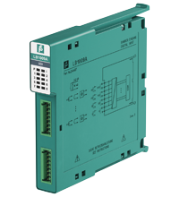
Digital Input LB1009A
- 8-channel
- Inputs Ex ic
- Installation in Zone 2 or safe area
- Dry contact or NAMUR inputs
- Positive or negative logic selectable
- Simulation mode for service operations (forcing)
- Line fault detection (LFD)
- Permanently self-monitoring
- Module can be exchanged under voltage


Please note: All product-related documents, such as certificates, declarations of conformity, etc., which were issued prior to the conversion under the name Pepperl+Fuchs GmbH or Pepperl+Fuchs AG, also apply to Pepperl+Fuchs SE.
Folhas de dados: Dados técnicos do LB1009A
| Descrição do Produto |
|---|
| Digital Input |
| Slots | ||
|---|---|---|
| Occupied slots | 1 | |
| Supply | ||
| Connection | backplane bus | |
| Rated voltage | 12 V DC , only in connection with the power supplies LB9*** | |
| Power dissipation | 1.55 W | |
| Power consumption | 1.55 W | |
| Internal bus | ||
| Connection | backplane bus | |
| Interface | manufacturer-specific bus to standard com unit | |
| Digital input | ||
| Number of channels | 8 | |
| Sensor interface | ||
| Connection | NAMUR sensor | |
| Connection [2] | volt-free contact | |
| Connection [3] | Usage without connection to areas where there is a risk of explosion: active signals, mechanical contacts, NAMUR sensors, 2-wire sensors If the device has been operated in general electrical systems that are not connected to areas where there is a risk of explosion, the device cannot then be used in electrical systems that are connected to areas where there is a risk of explosion. Usage with connection to areas where there is a risk of explosion: mechanical contacts, NAMUR sensors | |
| Connection | Terminals 1+, 2-, 3+, 4-, 5+, 6-, 7+, 8-, 9+, 10-, 11+, 12-, 13+,14-, 15+, 16- | |
| Rated values | acc. to EN 60947-5-6 (NAMUR) | |
| Switching point/switching hysteresis | 1.2 ... 2.1 mA / ± 0.2 mA | |
| Voltage | 8.2 V | |
| Internal resistor | 1 kΩ | |
| Line fault detection | can be switched on/off for each channel via configuration tool , active signals (24 V, 5 V) without line fault detection | |
| Connection | mechanical switch with additional resistors (see connection diagram) proximity sensors without additional wiring | |
| Short-circuit | < 360 Ω | |
| Open-circuit | < 0.35 mA | |
| Digital signals (active) | Use in safe area: configurable 24 V 5 V | |
| Switching point: ON | > 8 V > 2.7 V | |
| Switching point: OFF | < 3 V < 2.3 V | |
| Minimum pulse duration | 15 ms | |
| Indicators/settings | ||
| LED indication | Power LED (P) green: supply Diagnostic LED (I) red: module fault , red flashing: communication error , white: fixed parameter set (parameters from com unit are ignored) , white flashing: requests parameters from com unit Status LED (1-8) red: line fault (lead breakage or short circuit) , yellow: signal (per channel) |
|
| Coding | optional mechanical coding via front socket | |
| Directive conformity | ||
| Electromagnetic compatibility | ||
| Directive 2014/30/EU | EN 61326-1:2013 | |
| Conformity | ||
| Electromagnetic compatibility | NE 21 | |
| Degree of protection | IEC 60529 | |
| Environmental test | EN 60068-2-14 | |
| Shock resistance | EN 60068-2-27 | |
| Vibration resistance | EN 60068-2-6 | |
| Damaging gas | EN 60068-2-42 | |
| Relative humidity | EN 60068-2-78 | |
| Ambient conditions | ||
| Ambient temperature | -40 ... 60 °C (-40 ... 140 °F) , 70 °C (non-Ex) | |
| Storage temperature | -40 ... 85 °C (-40 ... 185 °F) | |
| Relative humidity | 95 % non-condensing | |
| Altitude | max. 2000 m | |
| Shock resistance | shock type I, shock duration 11 ms, shock amplitude 15 g, number of shocks 18 | |
| Vibration resistance | frequency range 10 ... 150 Hz; transition frequency: 57.56 Hz, amplitude/acceleration ± 0.075 mm/1 g; 10 cycles frequency range 5 ... 100 Hz; transition frequency: 13.2 Hz amplitude/acceleration ± 1 mm/0.7 g; 90 minutes at each resonance |
|
| Damaging gas | designed for operation in environmental conditions acc. to ISA-S71.04-1985, severity level G3 | |
| Mechanical specifications | ||
| Degree of protection | IP20 when mounted on backplane | |
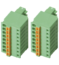
| Connection | removable front connector with spring terminal (0.14 ... 0.5 mm2) | |
| Mass | approx. 90 g | |
| Dimensions | 16 x 100 x 102 mm (0.63 x 3.9 x 4 inch) | |
| Data for application in connection with hazardous areas | ||
| Input | ||
| Voltage | 10 V | |
| Current | 12 mA | |
| Power | 30 mW (linear characteristic) | |
| Certificate | EXA 13 ATEX 0037X | |
| Marking |  II 3 G Ex nA [ic] IIC T4 Gc II 3 G Ex nA [ic] IIC T4 Gc |
|
| Galvanic isolation | ||
| Input/power supply, internal bus | safe electrical isolation acc. to EN 60079-11, voltage peak value 375 V | |
| Directive conformity | ||
| Directive 2014/34/EU | EN IEC 60079-0:2018+AC:2020 EN 60079-11:2012 EN 60079-15:2010 |
|
| International approvals | ||
| ATEX approval | EXA 13 ATEX 0037X | |
| IECEx approval | ||
| IECEx certificate | IECEx EXA 13.0003X | |
| IECEx marking | Ex nA [ic] IIC T4 Gc | |
| General information | ||
| System information | The module has to be mounted in appropriate backplanes (LB9***) in Zone 2 or outside hazardous areas. Here, observe the corresponding declaration of conformity. For use in hazardous areas (e. g. Zone 2 or Zone 22) the module must be installed in an appropriate enclosure. |
|
| Supplementary information | EC-Type Examination Certificate, Statement of Conformity, Declaration of Conformity, Attestation of Conformity and instructions have to be observed where applicable. For information see www.pepperl-fuchs.com. | |
Classifications
| System | Classcode |
|---|---|
| ECLASS 13.0 | 27210121 |
| ECLASS 12.0 | 27210121 |
| ECLASS 11.0 | 27210121 |
| ECLASS 10.0.1 | 27210121 |
| ECLASS 9.0 | 27210121 |
| ECLASS 8.0 | 27210121 |
| ECLASS 5.1 | 27210120 |
| ETIM 9.0 | EC001485 |
| ETIM 8.0 | EC001485 |
| ETIM 7.0 | EC001485 |
| ETIM 6.0 | EC001485 |
| ETIM 5.0 | EC001485 |
| UNSPSC 12.1 | 39121008 |
Details: LB1009A
Datasheet: LB1009A
| Datasheet | Tipo de Arquivo | Tamanho do Arquivo |
|---|---|---|
| Datasheet LB1009A | 864 KB | |
| Datenblatt LB1009A | 858 KB |
Documents: LB1009A
CAD+CAE: LB1009A
| CAD | Tipo de Arquivo | Tamanho do Arquivo |
|---|---|---|
| CAD 3-D / CAD 3-D | STP | 1453 KB |
Approvals+Certificates: LB1009A
| Certificates | Tipo de Arquivo | Tamanho do Arquivo |
|---|---|---|
| Brasil TUV Rheinland Brazil | 1224 KB | |
| Bureau Veritas (Maritime) Marine | 590 KB | |
| China SITIIAS CCC Ex Certificate | 1374 KB | |
| EXA IECEx Certificate of Conformity Non-Sparking nA | LINK | --- |
| Europe ATEX Category 3 G | 2198 KB | |
| Lloyd's Register Marine | 557 KB | |
| South Africa MASC | 730 KB | |
| Declaration of Conformity | ||
| EU Declaration of Conformity (P+F) / EU-Konformitäterklärung (P+F) | 1141 KB | |
| UK Declaration of Conformity (P+F) / UK-Konformitäterklärung (P+F) | 1137 KB |
Produtos Relacionados: LB1009A
| Accessories | ||||||
|---|---|---|---|---|---|---|
|
||||||


O nosso gateway LB/FB PROFINET abre as possibilidades para aplicações IIoT 4.0 nas indústrias de processos.


Pepperl+Fuchs Ltda.
Rua José Versolato, 111
Domo Corporate Tower, Conjunto 144
09750-730 São Bernardo do Campo, SP
Brasil
vendas@br.pepperl-fuchs.com
 +55 11 4007 1448
A Pepperl+Fuchs é líder na fabricação e no desenvolvimento de sensores e componentes eletrônicos para o setor global da automação industrial. Inovação contínua, qualidade e crescimento constante garantem o nosso sucesso há mais de 70 anos. Empregamos mais de 6.300 colaboradores em todo o mundo e contamos com fábricas próprias na Alemanha, Estados Unidos, Cingapura, Hungria, Indonésia e Vietnã, todas com certificação ISO 9001.